Your coil is generating a magnetic field at a certain frequency, keep in mind the magnetic field is going to 'attenuate' by the the inverse cube of the distance (magnetic field=1/(distance^3)). I'll give you a hint as to what you'll find. Then find the magnetic field through the coil (you'll need to know the area of the coil and the turns.) Then calculate what kind of energy you need at the input coil. Once you know the current use the equations located in this online textbook in chapter 11 Inductance and Magnetic energy (Yeah it requires math). You can either simulate it with a spice package or place a meter between the coil and transistor. Have you tried finding the current through the coil? Find the current through the coil. The number of turns of the coil is 300 instead of 275. My supply voltage was 10 volts because I don't have a battery of 9 volts.
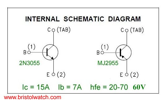
HOW TO USE 2N3055 TRANSISTOR HOW TO
I need to know how to achieve a good wireless range? and What controls the range? Is it supply voltage, the base resistor or something else? I need a good range, something like 5 or 10 cm. When I put the florescent lamp inside the coil it lights up. The other terminal of the coil is not connected (open circuit). I connected the high voltage terminal to one of the coil's terminals. I brought a wire and modified its shape to be round (a circle). When I approach a florescent lamp, It does not light up. The second problem is that the circuit does not provide enough range. How can I get rid of the very high temperature of the transistor. I burnt my transistor due to excessive heat. The major problem is that the transistor becomes very hot quickly. Since the speaker is a reactive load (especially at high audio frequencies), the reactance is reduced via the 100nf, 10Ω resistor –helps prevent oscillation.I build this circuit and it works but I have two problems. The 1500uf coupling cap keeps the DC portion of the output bus voltage off the speaker. In this way, the anode of the capacitor actually transcends the bus voltage when the output bus goes positive so that the BC286 has lots of base drive and can easily turn on fully. The 100-200uf capacitor is a “bootstrap” capacitor that couples the output bus to the 1-3K pullup resistor. The lower 2N3055 is connected to the BC287 in a composite connection that essentially turns the BC287 into a high current gain PNP transistor. The complementary transistors are both connected in the common collector configuration (emitter followers) so they have essentially unity voltage gain.Ĭoupled to the BC286 is the 2N3055 in a Darlington configuration.
If the bases of these two transistors were tied together, it would be a zero bias class B, but the bias regulator develops just enough voltage to put the complementary transistors just on the edge of conduction.

The BC107 is the bias regulator that develops approx 3 junction drops (1.95V) to properly drive the complementary transistors (top BC286 and the BC287). C1 and the resistor above it also provide frequency comp by reducing the AC feed back to the input stage. It is the high voltage gain element and requires a frequency compensation cap (C2) to prevent oscillation. The top left capacitor and resistor are noise decoupling for the bias source for the input transistor to keep it from amplifying the power supply noise and ripple.Ī signal is picked off the collector resistor to drive the base of the lower BD286.

With feedback as such, it has essentially unity AC and DC gain. It also regulates the DC operating point of the output bus. The PNP input stage is configured as a common emitter amplifier with lots of current feedback through the emitter resistor that is tied to the output bus.


 0 kommentar(er)
